Recipe for a Cubical Quad single-element – By Greg
N3BYR
(Metric and Standard Measurements included!)
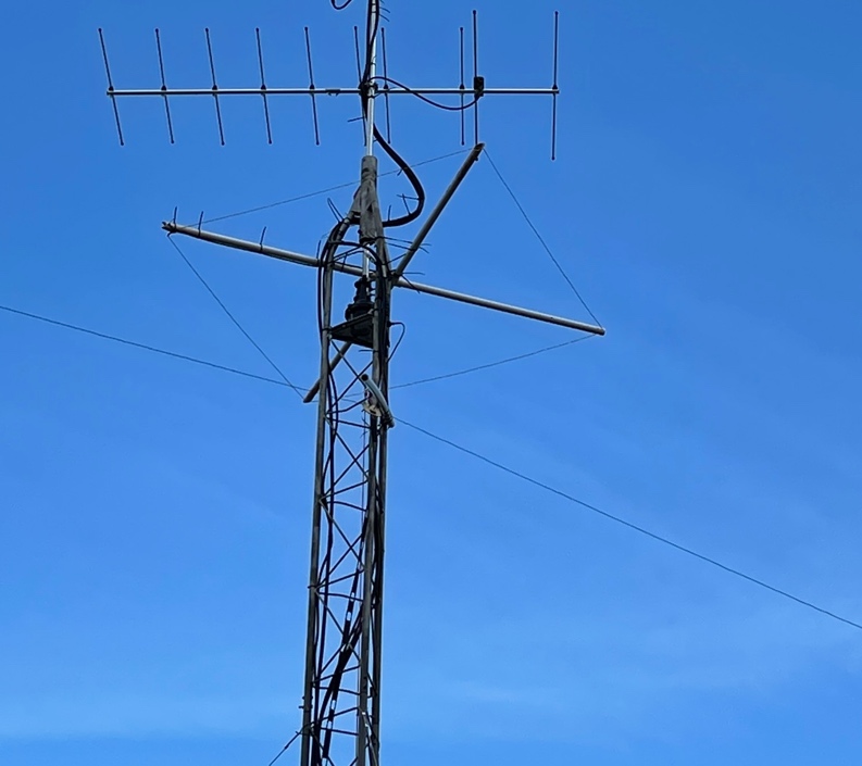
(The N3BYR PVC Cubical Quad 6-meter variant at the
rotor level of my tower)
This is an easy way to make a single
element cubical quad for any band, for this example I will use 50.200Mhz. I recommend
reading the entire piece before attempting to make the antenna, this makes the
process flow smoother than just going to town willy-nilly. Before beginning
construction, consider the polarization, planned use, and mounting methods to
employ. If you are using the antenna for repeaters or require a vertical
polarization you will need to pay close attention to the orientation of the
feed point. Cubical antennas exhibit some higher gains over a dipole in ‘Isotropic’
conditions, those gains can be even higher over real ground but are not garunteed. Gains in Isotropic can be roughly 3.25dBi versus
the ½ wave dipole at 2.15dBi. The Cubical Quad is a full wavelength antenna and
presents a 100-ohm impedance at the feed point for a square antenna. The feed
point will need to be matched to a 50-ohm feedline for a 1:1.5 or less SWR. Because
the cubical quad is electrically short (closed), there is a small factor of
noise reduction for your noise floors. Don’t be fooled by the math… it’s very
simple, I promise!
Let’s start with constants in our example antenna:
Speed of Light: 299,792,458 meters per second in a
vacuum
Frequency: 50,200,000 Hz (Note we are using Hz!)
Meters to Feet: Multiple meters by 3.28
*Velocity for matching coax: 0.66 or 66%
This example uses a piece of 75-ohm coax with a VF
(Velocity Factor) of 0.66 or 66%, which is the penalty speed essentially that
we need to know. This VF is only critical on the matching stub coax, and you
must know the VF for the 75 ohm section of coax. For
most foam dielectric coax the VF is in the 80% ballpark, solid dielectric is
typically in the 60% ballpark.
For the main loop wire, there is typically ~95%
velocity factor for wire. I have found with time that considering this velocity
factor is moot. Calculating the wavelength for the main loop without the
velocity factor will get you a little more length, which adds to wiggly room to
tighten up the VSWRs if they are not acceptable. The thicker your main loop
wire is, the more bandwidth you will see for good SWRs. Using 14ga wire versus
using 8ga wire will provide more frequency range and provides more surface
area. RF travels along the surface of a wire, not inside the wire.
We will do the very easy math below for our example
antenna. We will calculate the loop total length, calculate each side, and determine
our frame/support dimensions. You will likely need to google a triangle
calculator to get the support lengths… there are many free triangle calculators
on the web! You can use “https://www.calculator.net/triangle-calculator.html”
if the site exists when you are reading this. After we calculate the above, we
will also calculate the ¼-wave matching stub for the 75-ohm coax. Then we will
discuss polarization and orientation, and assembly of the parts.
The
Math
Wavelength
Speed
of light / Frequency in Hz = 1 wavelength loop in meters
299,792,458
/ 50,200,000 = 5.972 meters (Ever wonder why its called ‘6 meters’?)
Convert
meters to Feet
5.972
* 3.28 = 19.58816 (Don’t round this out just yet) Save this number! We need it still…
We
know that its 19 feet, but to find the inches just multiply the decimal value
by 12…
0.58816
* 12 = 7.05792 inches… let’s round up to the nearest 1/16th inch
(0.0625): 7 1/16”
Our
loop wire should start at 19 feet, 7 1/16 inches.
Find
each side length
Take
the total in decimal, this will make life easier, and divide by 4 and convert…
19.58816
/ 4 = 4.89704 convert inches again (0.89704*12 = ~10.76 or 10 ¾ inches) = 4’ 10
¾”
Save
the number above in decimal… we will need it again soon!
Determine
the frame/support arms needed
For this part we need to use a triangle calculator
just to save time and energy! Because there is an easily identifiable triangle in
this shape, and it’s a right angle, we can find the rest of the support needs quickly.
Consider the 90-deg. angle in the center, and the 45-deg. angles on the ends,
then calculate your triangle to get the length from the center to the point.
Multiply this by 2 for a whole support. If you are using PVC like mine, you
only need from center to point.
Once you put in the equation to a
triangle calculator, for this example you will find the center to point
distance is ~3.406. For my antenna I rounded up to 3.5 feet (3’ 6”). You can
double that to 7 feet if you are using two support rods. This will require a
hole drilled in the support, or other way to fasten the wire to the support.
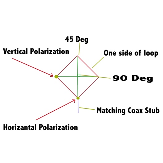
Polarization
Considerations
In the above diagram there are two
possible feed points for the antenna. If the antenna is standing as shown
supported at the bottom by mast or other method, the two feedpoints
will provide the identified polarization. If the antenna is laying flat
(horizontal), regardless of where the antenna feed point is located, the
antenna will exhibit a horizontal polarization. Also
with the antenna flat, the radiation pattern will be relatively unidirectional.
If the antenna is upright like the diagram, the lobes will be to the front and
back, like a dipole radiation pattern.
The
Matching Stub
Because a cubical quad antenna produces a
100-ohm impedance, it needs to be matched for a 50-ohm feedline. The simplest
way to do this without a 2:1 balun is a single piece of 75-ohm coax that is
equal to the electrical length of ¼ wave. The velocity factor of the coax must
be considered for the proper length. We already determined the non-corrected ¼ wavelength
above when we determined that each side of the loop needs to be 4.89704 feet! So all we need to do now is determine the velocity factor,
and correct the length. In this example we are using coax with a 0.66 VF, make
sure you know the VF for your 75-ohm coax! Here is the last of the maths…
¼ wavelength * Velocity Factor = Matching coax stub length
4.89704 * 0.66 = 3.232 (We can round up to 3.25
safely) 3 feet and 3 inches
The matching 75-ohm coax goes at the feed
point of the antenna to connect to the 50-ohm coax feedline to the radio… that’s
it! Now assemble what you need for parts and wire, and
build a cubical quad antenna.
Future
Considerations
A cubical quad single element is a neat antenna
and can be built to where it can be disassembled for easy transport of SOTA,
POTA, Field Day, or other excursions with your radio gear! It will also get you
just slightly higher gains than a simple dipole, and
reduce some of the noise floor due to being an electrically short antenna. This
is also a building block for a Cubical Quad beam antenna, and I might write
another article to describe how to build cubical beam. I have made several in
the past and they are very effective! Another consideration is you can ‘Nest’
multiple cubical antennas inside each other with less loss on gain than other style
antennas. Consider making a 6-meter single element, and nest 2-meter,
1.35-meter (220), or 70cm cubical within the same support.
73’s
de N3BYR!